
Controlling the printer
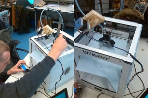
We continued this week with tests of some ideas but also with preparing our printer. The new fan arrived and we were able to insert the filament. We couldn’t use the Ultimaker Originals control screen to extrude.
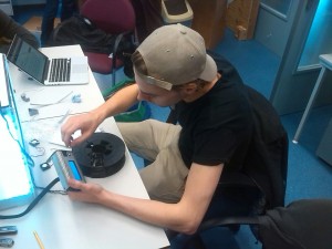
Looking into all the options on the control screen of the Ultimaker Original.
After some tests we concluded that the hardware was working but it didn’t respond to the commands. The solution was to control the Ultimaker using “Pronterface” on the computer.
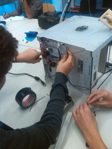
Testing all the connections on the PCB.
Another program that is used is “Repetier Host”. This allows us to open and edit g-code files. It also shows how the print will look like by reading the g-code. G-code is a geographic file that has to be send to the printer to give it his command.
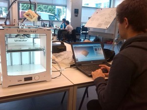
Controlling the Ultimaker by using the computer.
Our first print
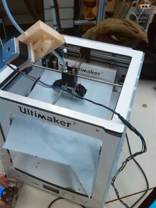
It was time for our first print! When it started printing, we saw that the printing bed wouldn’t go to the desired height. Due to the fact an Ultimaker Original is smaller than an Ultimaker 2, the end-stops prevent the bed going higher. We managed to cheat the system a little by moving the printing bed further up while printing. This hack had to be done every time a new print starts because of the offset we applied was removed after finishing a print. Using the technique of moving the bed while printing we could print some small shapes, but the start of the print always looked bad.
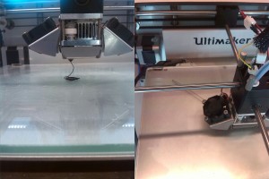
The distance between the nozzle and the printing bed is much to large, resulting in inaccuracy.
Calibrating and moving forward
To solve the problem permanently, the end-stops had to be disabled in the configuration.h file. By doing that the bed could go unlimited high and we could calibrate the printer. The calibrating part was done by the half of the group. The other two members worked on a way to cut the fiber each time the printer moves without extruding plastic (travel move).
Calibration of the Ultimaker.
We managed to print a little cube on the right distance of nozzle and bed. We began to master the different settings of printing. The cube had some little deformation. This is because our object cools down to quick. We are using ABS-filament, which is very temperature sensitive. But despite that, it was a nice achievement.
The Ultimaker, ready for print (except for the piece of paper that was used for the calibration).
The cutting device that was being designed should be placed on the printer head. This device contains a stepper motor and a spring that will move down a little, rotate a razor blade connected to the stepper motor and cut of the Kevlar fiber at the nozzle so the printer head can move freely.
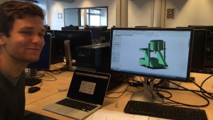
Design process of the cutting mechanism.


