
Last week
This is the last week of the project. Next week we have to present our findings and final design on a science fair. Our goal this week is to optimize a print, which can be tested on its strength and compared with the same print without fiber.
Final design
The final designs will be made by using all the solutions and methods we have find during the past weeks. They will be tested to see the improvement of a fiber reinforced print.
First test print
Our first print that will tested is a chain link. The choice of a chain link is because it is very easy to attach it and make a test set-up for it. The chain link can easily be hung and we will augment the load which we hang at the other side of the link. The chain link was designed with the following properties:
- Length: 50 mm
- Thickness: 6 mm
- Insider radius: 4 mm
- Outer radius: 10 mm
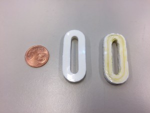
The chain links, left without fibers and right with fibers. There is also a coin of 5 euro cent as reference.
Script to remove travel moves
To make it possible to print almost every gcode, because we won’t work with a cutting extension, we had to make sure that there are no travel moves. If it would have a travel move the fiber, that is attached to the nozzle and the print, will either break or pull the print when moving without extrusion. We made a Python-script which changes the travel moves into printable moves. After a few days of work it’s finally finished! Here’s how it works step by step. Note that this example is not perfect, since this first layer has different settings.
- First the script opens a gcode file, and copies all the lines to a new file. It searches the the last line G1 before a travel-move G0. G0 is a fast movement without extrusion.
- The G1 line remains the same in the new file on the right side.
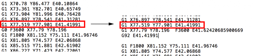
The last line G1 before a travel-move G0 is marked in red.
- The G0 is replaced by a G1, which is a slower movement. By calculating the length of the actual movement and multiplying this length with an extrusion constant we get an estimated E, which we add at the end of the new line G1. (marked green).
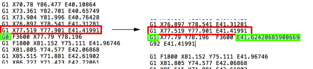
Here the change of G0 to G1 and the new E value are shown.
- To reset the extrusion-settings we make a new line with G92, and add the last E value of the original G1.
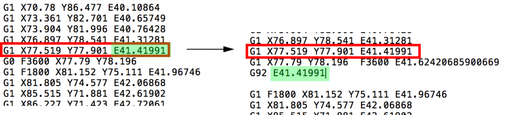
Here is an example of how the G92 line looks. In this case the E value of the original G1 line was E41.41991.
- And the code continues!


