Author Archives: Lennard van der Vaart

Week 5: First Tensile Test!

Tests

Yesterday the strength was of the printed rings, with and without fibers. First we tried 4 rings: 4 x 6mm PLA, 4 x 6mm PLA with kevlar fibers, and 5 x 6mm PLA, and 5 x 6 mm PLA with fibers. These were attached to the tensile testing with a rope.

IMG_0712

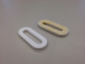
These are the 4×6 mm rings.

IMG_0713

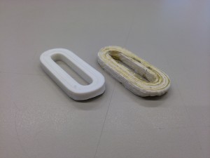
These are the 5×6 mm rings.

The tests are repeated with the same sort of rings to eliminated the small differences in quality.

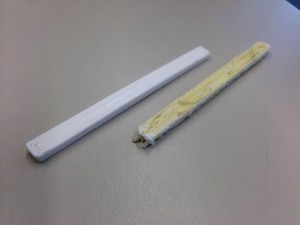
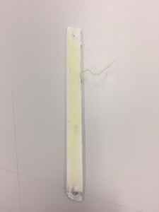
For the next bars we tried a bending-test. The 8 x 4 x 100mm PLA bars with fiber and without are used. The black bar is also made of PLA, but the white roll was finished.

IMG_0715

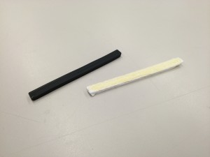
These are the bars of 8×4 mm; The black bar is also PLA but only a different color.

IMG_0727

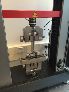
Set up of the 3 point bending-test.

Results

The results of the strength of the chain link (5 x 6 mm) were very promising. The one without fibers snapped at a force of 2337 Newton, which is about 258 kilograms. The one with the kevlar fibers broke at 3659 Newton, or 373 kilograms. This makes the link with fibers about 1.6 times stronger.

Schermafbeelding 2016-10-28 om 14.29.17

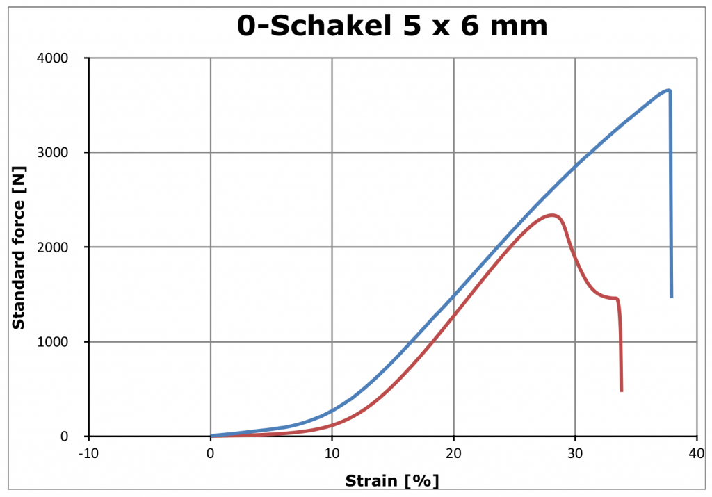
The red line is from the print without fibers, the blue one is with fibers.

Almost the same results came from the test of the other chain link (4 x 6 mm). The one with fibers is also significantly stronger. Without the fibers, it snapped at a force of 1952 Newton, which is about 199 kilograms. The link with the kevlar fibers broke at 2513 Newton, or 256 kilograms. This makes the link with fibers about 1.3 times stronger.

Schermafbeelding 2016-10-28 om 14.40.17

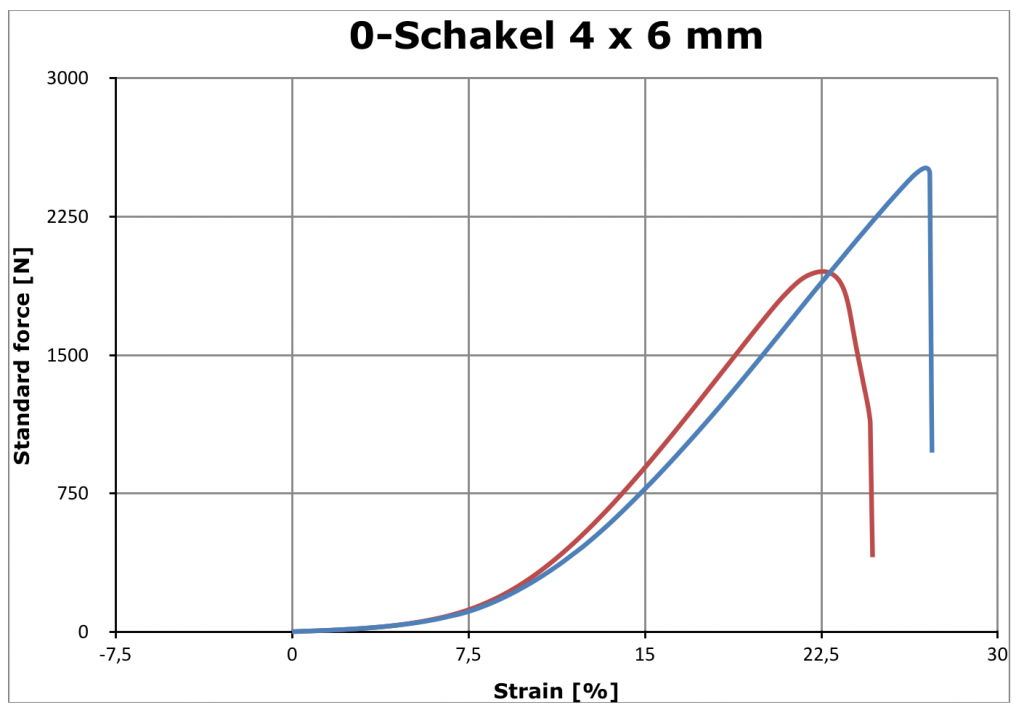
The red line is from the one without fibers; the blue one is from the link with fibers.

As you can see in both graphs the fibers suddenly snap. The PLA has more strain after the strongest point. The results of the Bending-test are coming soon.

In the video below you can see one of the PLA test prints being ripped apart in slow motion.

[youtube]https://www.youtube.com/watch?v=DkZEHcvoXqw[/youtube]


Week 4: First full prints!

Real fiber prints

After all the obstacles we were able to finally print some real geometric pieces with fibers!

14787594_1265217663517984_1741645280_o

The Ultimaker busy printing a fiber-reinforced piece.

The pieces we printed were a big step and although they weren’t perfect, it was the prove a big step in the right direction.

14800203_1265206136852470_1179325857_o

At the left there is a piece without fibers and at the right side the same piece was made using kevlar-fibers.

The kevlar-fibers don’t stick easily at the corner, and get pulled away. We’ve tried to prevent this from happening by pressing the fibers with a ruler to the base during the print.

[vimeo]https://vimeo.com/188796988[/vimeo]


Ratio calculating script

As previous mentioned, the ratio between fibers and filament has a crucial part in the system. Our previous approach had some variables which couldn’t be control totally. We wanted to find a way which calculated the exact ratio for each print. A python program scans through all the lines of the g-code and find the total length of all the printed parts and the total length that is extruded. The ratio between these two can be used to find the perfect settings. The total length can be seen as the required fiber length (the number of mm E2 has to extrude) and the total length that is extruded (the number of mm E1 has to extrude).  After testing and measuring the amount extruded by E1 it turned out to be approximately 1130 mm instead of the 1297 mm that was given in the g-code file. A second test turned out to be 1160 mm instead of the calculated 1297 mm. The error is due to a discontinuity between the steps that are send to the stepper-motor of the filament and to mm it extrudes. This in’t a problem because our fiber also has a thickness.

python script

Python script which calculates the total path length

excel script

Excel file with the measurements and calculations. This way the ratio is calculated.

DIY Nozzle

Because we used a nozzle of 1.2 mm, we decreased the pressure inside the nozzle. This pressure is needed to make sure the fiber is well embedded into the print. To build up the pressure, we had to make our own nozzles in which the narrow part is longer.

diy nozzle

The difference between the original nozzle and the one we have made is shown in this picture.

We made two nozzles, with each different diameters of the extrusion parts. One has a diameter of 0.8 mm and the other has a diameter of 1.2 mm. The rest of the nozzle is exactly the same.

The length of the narrow part was first 10.0 mm. This concluded in a too high pressure, since the filament was pushed outside of the nozzle at the upper part. We decreased the length with steps of 2.5 mm, until the leaking stopped. We came to a length of 5.0mm.

dripping nozzle

Too high pressure in the nozzle results into leakage.

The nozzle with a diameter of 0.8mm often jammed, which the 1.2mm nozzle did not do. Therefore, we decided to carry on with the 1.2 mm nozzle. The fibres that we now print are more integrated into the filament. One can see that the fibres are laid out very straight within the print, which increases their strength. This is most-likely because the pressure in the nozzle is higher now.

printed balk

THe fibers that are printed are parallel to each other which makes the print much stronger.

Week 4: Fibers viewed by microscope!

Our fibers viewed by a microscope

Last friday we had a look at the printed or wound fibers with a microscope.  The dark black carbon-fibers are fragile. They are wound around a piece of PLA but some of them are broken.

IMG_7836

A cluster of carbon-fiber wound around PLA filament.

The Kevlar was much easier to wind, but the quality or stickiness of the fibers to the PLA was much different along the same piece. As shown in thenext three pictures, some windings are tight, as others are more or less coming off:

IMG_7849

IMG_7850IMG_7848 
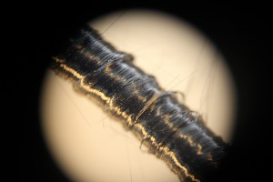
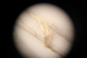
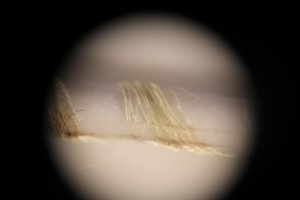
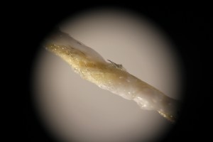
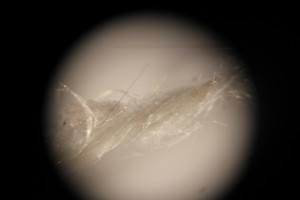
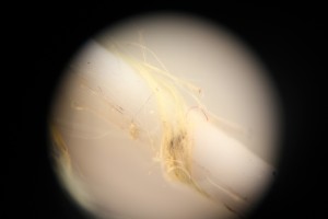
Kevlar-fiber wound onto PLA-filament but with different tightness.

This next piece of PLA was stuck in the nozzle. After pulling it out, the PLA was actually connected to the fibers. The fibers were split and got placed within the molten PLA. However, this amount of PLA is too low to print, since the layers won’t stick together.

IMG_7831

A piece of molten PLA with some kevlar-fiber included.

The same test was done with glass-fibers, but these don’t provide any strength since they break very easily.

IMG_7837

Glass-fibers wound around piece of PLA but they are clearly broken.