Author Archives: Rick van der Leer

Summary

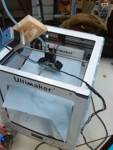
The goal of the project was to reinforce FDM with fibers. The Markforged printer can do this, however it is very expensive for hobbyists and small companies. This project focuses on modifying an Ultimaker 2 so that it can print fibers. This technique is way more accessible.

Finding the perfect winding ratio

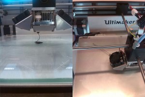
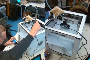
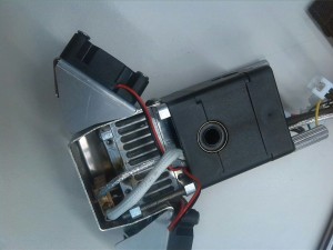
The way we impregnate our filament with fibers is by winding the fibers around the filament just before it enters the nozzle. We do this because the length of the extruded filament is longer than the length of the filament that goes into the nozzle, thus more fiber must enter the nozzle per mm of filament. The winder is powered by a stepper motor and is connected to the PCB as a second extruder.

[vimeo]https://vimeo.com/188796988[/vimeo]

The winding ratio is configured using the M163 gcode command, which allows you to set a ratio between the two extruders (extruder and winder). First the steps per mm were defined (M92), by measuring the distance extruded by distance given. This means that if we tell the extruder to extrude 1 meter of filament that we measure the distance extruded and divide the current steps per mm by the ratio between the two distances.

The next step was changing the ratio (M163) in such a way that the winder makes two windings per mm of filament. This ratio is later used in an excel file to find the perfect winding ratio for each print.

In order to find the perfect winding ratio the ratio between the total travel path of the nozzle and the amount of filament extruded must be found. We wrote a python script that opens a gcode file, finds all the moves of the printer and adds the distance traveled together. It also finds the total amount of extruded filament (the E value in a G1/print command). The ratio between these values is the ratio between the length of fiber required and the length of filament inserted. This way you can calculate the perfect winding to extrusion ratio for each gcode. One flaw with this technique is that there is a small ratio between the calculated amount of extruded filament and the measured amount of extruded filament (this is probably due to a mistake in the steps per unit, or a printer inaccuracy) therefore we added an additional ratio to compensate for this. This will eventually give you the right values for M163 (the ratio between the extruders) and M221, which determines the speed of the flow (M221 is important because the ratio for the winder is larger than one, but the M163 command does not understand values larger than one).

Preventing clogging of the nozzle

A major problem with fiber printing is forcing a thick fiber and filament through a small nozzle. If the nozzle is too small,  it will get clogged, but if the nozzle is too big there is not enough pressure to push the winded fiber into the filament for better fiber-filament adhesion.

During the project we used many different fibers and varying thicknesses. We found that thinner fibers were easier to print, but of course a thinner fiber means less strength. We also tested the difference between glass, carbon and aramid fibers. Glass fibers were too fragile to be bent around a small filament and would often break. Carbon and aramid fibers were more flexible and worked well. Our final product contained only aramid fibers because we did not have thin strains of carbon fibers, which were necessary to prevent clogging the nozzle.

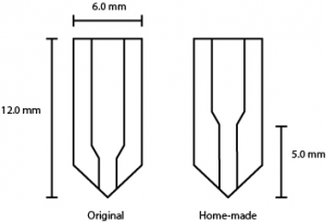
Because we used an Olsson block we could easily design and change our own nozzles. We wanted the nozzle to be big but still apply enough pressure on the filament. Therefore we made a nozzle with a longer thin part at the tip to increase pressure. We tested different tip lengths and different nozzle diameters and eventually used a nozzle with a diameter of 1.2 mm and a 5.0 mm long narrow tip.

diy nozzle

Making printable objects

When using a normal slicer to slice your 3D objects the printer will almost always include some travel moves (G0). A travel move is a move that the printer makes without extruding any filament. This is a problem for fiber printing since the fiber is continuous. The first plan was to make a cutting device on the nozzle that would cut the fiber before any G0 commands. This unfortunately did not work and thus we decided to just change all G0 commands in to G1 commands (print commands).

Another problem we had while making our final chain links was that the slicer we used made each layer with half of the circles going clockwise and the other half going counter-clockwise. This results in a weak spot in the print where the direction is reversed. To solve this we made another program that finds all the circles that go counterclockwise and changes their direction to clockwise. This resulted in an increase in strength of 191% instead of 156% compared to prints with no fibers.

Week 6: Science fair

Science fair

IMG_5215riktig

Tuesday the 1st of November we had the science fair in the main hall of the Industrial design building. At this science fair we demonstrated our work. A fun way to demonstrate the strength of our fiber prints was by hanging a couch on the chain links we printed. Just to be safe we first hung the couch from four chain links, which we later reduced to two. Even two links is a little on the safe side, as one link could easily support the couch and 6 people and still have a safety margin of 1.3. The swinging couch received a lot of attention from the students walking around. We presented our final product at our own stand, complete with live 3D printing, a poster and some of our test products. At the end of the day, we decided to see how many people we could fit on the couch before something would break. When 6 people were jumping on the couch the steel links connecting our fiber prints to the cables started to bend open. The fact that the construction did not fail at our links felt like a victory!

308c5af0-ce78-4642-822d-0975a4acc657


Week 2: Controlling the printer

Controlling the printer

We continued this week with tests of some ideas but also with preparing our printer. The new fan arrived and we were able to insert the filament. We couldn’t use the Ultimaker Originals control screen to extrude.

IMG_1208

Looking into all the options on the control screen of the Ultimaker Original.

After some tests we concluded that the hardware was working but it didn’t respond to the commands. The solution was to control the Ultimaker using  “Pronterface” on the computer.

IMG_1209

Testing all the connections on the PCB.

Another program that is used is “Repetier Host”. This allows us to open and edit g-code files. It also shows how the print will look like by reading the g-code. G-code is a geographic file that has to be send to the printer to give it his command.

5a215fa6-1dd4-4551-a16a-65057a990197

Controlling the Ultimaker by using the computer.

Our first print

It was time for our first print! When it started printing, we saw that the printing bed wouldn’t go to the desired  height. Due to the fact an Ultimaker Original is smaller than an Ultimaker 2, the end-stops prevent the bed going higher. We managed to cheat the system a little by moving the printing bed further up while printing. This hack had to be done every time a new print starts because of the offset we applied was removed after finishing a print. Using the technique of moving the bed while printing we could print some small shapes, but the start of the print always looked bad.

first print

The distance between the nozzle and the printing bed is much to large, resulting in inaccuracy.

Calibrating and moving forward

To solve the problem permanently, the end-stops had to be disabled in the configuration.h file. By doing that the bed could go unlimited high and we could calibrate the printer. The calibrating part was done by the half of the group. The other two members worked on a way to cut the fiber each time the printer moves without extruding plastic (travel move).

victor fixt

Calibration of the Ultimaker.

We  managed to print a little cube on the right distance of nozzle and bed. We began to master the different settings of printing. The cube had some little deformation.  This is because our object cools down to quick. We are  using ABS-filament, which is very temperature sensitive. But despite that, it was a nice achievement.

99723cb8-c092-4a0b-90bb-0c90fd9ed5d3

The Ultimaker, ready for print (except for the piece of paper that was used for the calibration).

The cutting device that was being designed should be placed on the printer head. This device contains a stepper motor and a spring that will move down a little, rotate a razor blade connected to the stepper motor and cut of the Kevlar fiber at the nozzle so the printer head can move freely.

5172a11c-258d-4c74-ae00-c0e796162504

Design process of the cutting mechanism.


Week 1: Get acquainted with the Ultimaker

When we first got the printer from Joris, we had to make “our” combined Ultimaker 2 work with the PCB of the Ultimaker Original. There was also a fan which had to be replaced. This fan is needed so that the filament does not solidify within the Ultimaker. Due to closure of the PMB at the IO faculty we could not ask them for a replacement, therefor we ordered one which should arrive on monday.

IMG_1213

The detached nozzle head, with the missing fan.

In the meantime, we brainstormed about different solutions to the various problems that printing with fibers gives. The main challenges were the printing path, adhesion of the fibers to the filament and cutting the fiber whenever the printer has to make a move.

IMG_1212

Whiteboard with our brainstorm of multiple possibilities.

We started testing some of our ideas to see which of them are achievable.

Stan tested some ways to connect the fibers to the filament, with some degree of success.