Monthly Archives: October 2016

Week 6: Last improvements and test

Script to make same direction in path

The chain link we tested in the tensile testing machine has one design flaw. When sliced using Cura, the inner wall of the chain link is printed clockwise and the outer wall is printed counter clockwise. This resulted in a specific point on the chain link on which the fiber is not continuous but turns around. As a result, all links printed with fibers broke at the location of these turns.

To make our print stronger, python script was used. This script analyses the gcode and determines whether or not the path is clockwise or counter clockwise. If it is counter clockwise the program reverses the printing direction.

Reversing the printing direction proved a little harder than expected. This was because the E values in the gcode first had to be changed into a value for only that distance (since E values in gcode represent the total extrusion) before they could be moved around. Also the G0 (travel moves) commands had to be moved a little, since the final G1 (printing move) command per round ends up at the same position as the G0 before that round. If the order is reversed, the first G1 command moves the nozzle to the position it is already in while extruding material. This was solved by turning the coordinates of the G0 commands equal to the location of the first G1 command per round instead of the last.
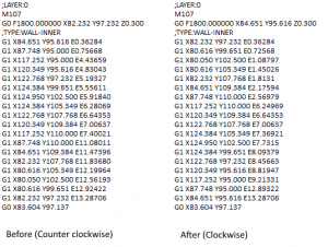
gcode swap

A part of the used gcode file is shown before and after running it through the script. The swap of lines can be seen.

The G0 command is needed to make this script work but can later be removed using the other python script.

Final Test

For our final print we chose the next specifications:

  • Length: 50 mm
  • Thickness: 8 mm
  • Insider radius: 7.5 mm
  • Outer radius: 20 mm
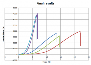
final results

Light blue (6731N, 686kg) and purple (7017N, 715kg): Chain link with fibers. Dark blue (3691N, 376kg), green (3203N, 326kg) and red (3930N, 400kg): Chain link without fibers.

The chain links with fibers broke at an average force of 6874 N (700.7 kg). The one without fibers broke at an average force of 3608 N (367.8 kg). The one with fibers is 1.9 times stronger then the one without fibers.

Week 5: First Tensile Test!

Tests

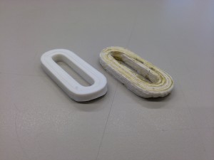
Yesterday the strength was of the printed rings, with and without fibers. First we tried 4 rings: 4 x 6mm PLA, 4 x 6mm PLA with kevlar fibers, and 5 x 6mm PLA, and 5 x 6 mm PLA with fibers. These were attached to the tensile testing with a rope.

IMG_0712

These are the 4×6 mm rings.

IMG_0713

These are the 5×6 mm rings.

The tests are repeated with the same sort of rings to eliminated the small differences in quality.

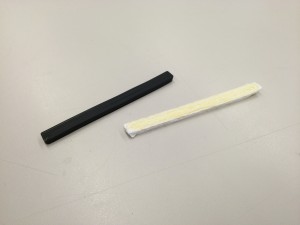
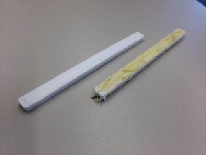
For the next bars we tried a bending-test. The 8 x 4 x 100mm PLA bars with fiber and without are used. The black bar is also made of PLA, but the white roll was finished.

IMG_0715

These are the bars of 8×4 mm; The black bar is also PLA but only a different color.

IMG_0727

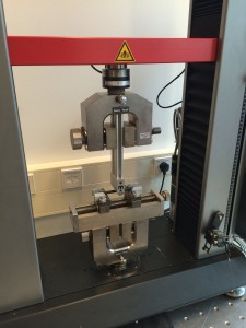
Set up of the 3 point bending-test.

Results

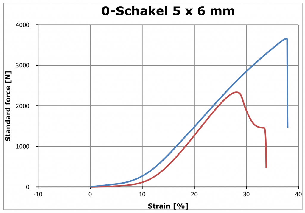
The results of the strength of the chain link (5 x 6 mm) were very promising. The one without fibers snapped at a force of 2337 Newton, which is about 258 kilograms. The one with the kevlar fibers broke at 3659 Newton, or 373 kilograms. This makes the link with fibers about 1.6 times stronger.

Schermafbeelding 2016-10-28 om 14.29.17

The red line is from the print without fibers, the blue one is with fibers.

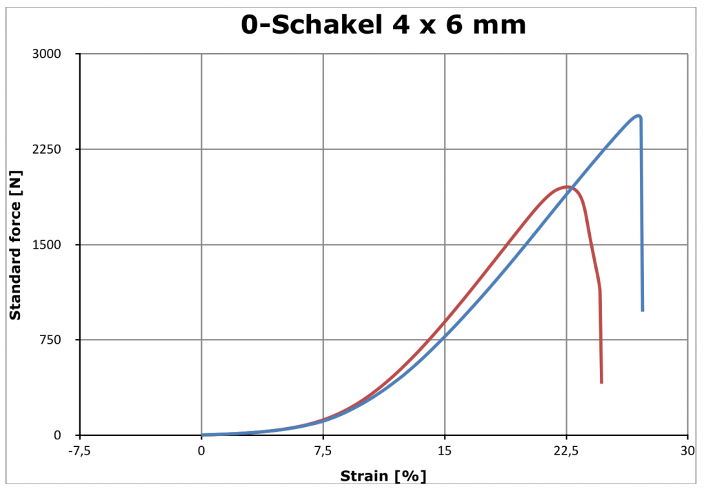
Almost the same results came from the test of the other chain link (4 x 6 mm). The one with fibers is also significantly stronger. Without the fibers, it snapped at a force of 1952 Newton, which is about 199 kilograms. The link with the kevlar fibers broke at 2513 Newton, or 256 kilograms. This makes the link with fibers about 1.3 times stronger.

Schermafbeelding 2016-10-28 om 14.40.17

The red line is from the one without fibers; the blue one is from the link with fibers.

As you can see in both graphs the fibers suddenly snap. The PLA has more strain after the strongest point. The results of the Bending-test are coming soon.

In the video below you can see one of the PLA test prints being ripped apart in slow motion.

[youtube]https://www.youtube.com/watch?v=DkZEHcvoXqw[/youtube]


Week 5: Final design

Last week

This is the last week of the project. Next week we have to present our findings and final design on a science fair. Our goal this week is to optimize a print, which can be tested on its strength and compared with the same print without fiber.

Final design

The final designs will be made by using all the solutions and methods we have find during the past weeks. They will be tested to see the improvement of a fiber reinforced print.

First test print

Our first print that will tested is a chain link. The choice of a chain link is because it is very easy to attach it and make a test set-up for it. The chain link can easily be hung and we will augment the load which we hang at the other side of the link. The chain link was designed with the following properties:

  • Length: 50 mm
  • Thickness: 6 mm
  • Insider radius: 4 mm
  • Outer radius: 10 mm
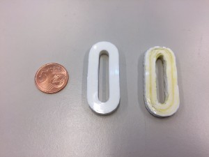
chain link

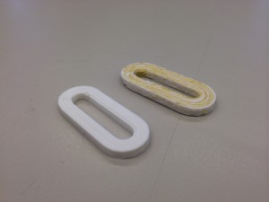
The chain links, left without fibers and right with fibers. There is also a coin of 5 euro cent as reference.

Script to remove travel moves

To make it possible to print almost every gcode, because we won’t work with a cutting extension, we had to make sure that there are no travel moves. If it would have a travel move the fiber, that is attached to the nozzle and the print, will either break or pull the print when moving without extrusion. We made a Python-script which changes the travel moves into printable moves. After a few days of work it’s finally finished! Here’s how it works step by step. Note that this example is not perfect, since this first layer has different settings.

  • First the script opens a gcode file, and copies all the lines to a new file. It searches the the last line G1 before a travel-move G0. G0 is a fast movement without extrusion.
  • The G1 line remains the same in the new file on the right side.
Before After 1

The last line G1 before a travel-move G0 is marked in red.

  • The G0 is replaced by a G1, which is a slower movement. By calculating the length of the actual movement and multiplying this length with an extrusion constant we get an estimated E, which we add at the end of the new line G1. (marked green).
Before After 2

Here the change of G0 to G1 and the new E value are shown.

  • To reset the extrusion-settings we make a new line with G92, and add the last E value of the original G1.
Before After 3

Here is an example of how the G92 line looks. In this case the E value of the original G1 line was E41.41991.

  • And the code continues!

Week 4: First full prints!

Real fiber prints

After all the obstacles we were able to finally print some real geometric pieces with fibers!

14787594_1265217663517984_1741645280_o

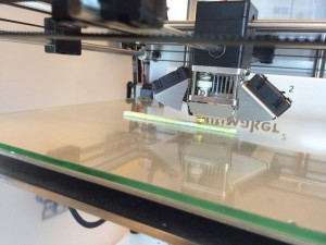
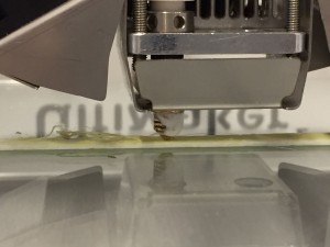
The Ultimaker busy printing a fiber-reinforced piece.

The pieces we printed were a big step and although they weren’t perfect, it was the prove a big step in the right direction.

14800203_1265206136852470_1179325857_o

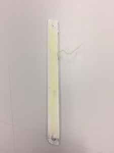
At the left there is a piece without fibers and at the right side the same piece was made using kevlar-fibers.

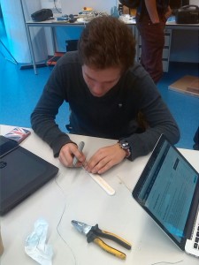
The kevlar-fibers don’t stick easily at the corner, and get pulled away. We’ve tried to prevent this from happening by pressing the fibers with a ruler to the base during the print.

[vimeo]https://vimeo.com/188796988[/vimeo]


Ratio calculating script

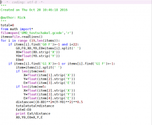
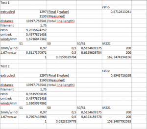
As previous mentioned, the ratio between fibers and filament has a crucial part in the system. Our previous approach had some variables which couldn’t be control totally. We wanted to find a way which calculated the exact ratio for each print. A python program scans through all the lines of the g-code and find the total length of all the printed parts and the total length that is extruded. The ratio between these two can be used to find the perfect settings. The total length can be seen as the required fiber length (the number of mm E2 has to extrude) and the total length that is extruded (the number of mm E1 has to extrude).  After testing and measuring the amount extruded by E1 it turned out to be approximately 1130 mm instead of the 1297 mm that was given in the g-code file. A second test turned out to be 1160 mm instead of the calculated 1297 mm. The error is due to a discontinuity between the steps that are send to the stepper-motor of the filament and to mm it extrudes. This in’t a problem because our fiber also has a thickness.

python script

Python script which calculates the total path length

excel script

Excel file with the measurements and calculations. This way the ratio is calculated.

DIY Nozzle

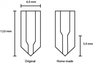
Because we used a nozzle of 1.2 mm, we decreased the pressure inside the nozzle. This pressure is needed to make sure the fiber is well embedded into the print. To build up the pressure, we had to make our own nozzles in which the narrow part is longer.

diy nozzle

The difference between the original nozzle and the one we have made is shown in this picture.

We made two nozzles, with each different diameters of the extrusion parts. One has a diameter of 0.8 mm and the other has a diameter of 1.2 mm. The rest of the nozzle is exactly the same.

The length of the narrow part was first 10.0 mm. This concluded in a too high pressure, since the filament was pushed outside of the nozzle at the upper part. We decreased the length with steps of 2.5 mm, until the leaking stopped. We came to a length of 5.0mm.

dripping nozzle

Too high pressure in the nozzle results into leakage.

The nozzle with a diameter of 0.8mm often jammed, which the 1.2mm nozzle did not do. Therefore, we decided to carry on with the 1.2 mm nozzle. The fibres that we now print are more integrated into the filament. One can see that the fibres are laid out very straight within the print, which increases their strength. This is most-likely because the pressure in the nozzle is higher now.

printed balk

THe fibers that are printed are parallel to each other which makes the print much stronger.

Week 4: Fibers viewed by microscope!

Our fibers viewed by a microscope

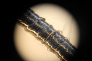
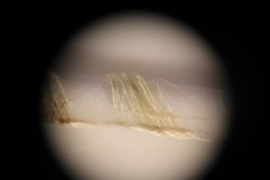
Last friday we had a look at the printed or wound fibers with a microscope.  The dark black carbon-fibers are fragile. They are wound around a piece of PLA but some of them are broken.

IMG_7836

A cluster of carbon-fiber wound around PLA filament.

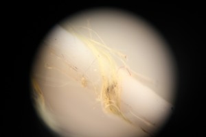
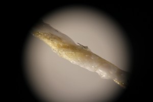
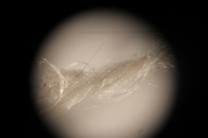
The Kevlar was much easier to wind, but the quality or stickiness of the fibers to the PLA was much different along the same piece. As shown in thenext three pictures, some windings are tight, as others are more or less coming off:

IMG_7849

IMG_7850IMG_7848 Kevlar-fiber wound onto PLA-filament but with different tightness.
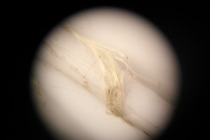
This next piece of PLA was stuck in the nozzle. After pulling it out, the PLA was actually connected to the fibers. The fibers were split and got placed within the molten PLA. However, this amount of PLA is too low to print, since the layers won’t stick together.

IMG_7831

A piece of molten PLA with some kevlar-fiber included.

The same test was done with glass-fibers, but these don’t provide any strength since they break very easily.

IMG_7837

Glass-fibers wound around piece of PLA but they are clearly broken.

Week 3: Visiting Ultimaker and Printing Fibers

Visiting Ultimaker

On the first day of the week we visited the office of Ultimaker in Geldermalsen. We brought our 3D-printer so we could show them what we did so far. We received some PLA filaments which we could use. These are more easy to work with than ABS filaments.

IMG_1216

A model which is shown at Ultimaker. Joris also helped on this project.

New Fibers

We ordered three new non-prepreg fibers to look at there properties. The three new non-prepreg fibers, namely aramide-, glass- and carbon fiber, arrived. We tested how these would stick to filaments by pressing them together with a soldering iron. We found out that a thin cluster works better and results in a tighter wound fiber around the filament. After printing the fiber is also more enclosed into the filament.

IMG_1229

A thick thread of carbon fiber is wound around a piece of filament.

Wrapping the fibers

By using the extension that was provided by Joris, we could test the winding of the fiber around the filament. The use of windings is due to the fact the filament will be printed on a larger distance in the print. We had to find the right ratio between the fiber and the filament. The biggest problem with the winding ratio is if the settings are changed while converting the STL file into g-code the perfect winding ratio changes. The ratio can be controlled by manipulate the speed of the wrapping according to the speed of the extrusion of filament. This way the amount of fiber around the filament can be regulated. The ratio was find y first making sure that the stepper motor of the filament extrudes 1mm of filament when it extrudes on 100% and then we measuring the amount of steps that is needed to rotate the winder ones. Taking in account the gear and fine-tuning the entire system we found a ratio which has variables such as nozzle head and layer height.

IMG_1227

The end of the winder with an open part which holds everything together but shows the windings.

Homemade Prepreg-fibers

We tried to make our own spools of thin fibers. This gave some challenges since the fiber thread consists of thousands of very thin fibers, it clusters when it is put on a spool. We decided to glue the tiny fibers of one thread together with a glue stick.

IMG_1228

Inspection of the “glued” treads.

After letting them dry, we put them on spools, and we had our homemade (low-budget) prepreg-fibers. We put these fibers on the Ultimaker, and were able to get the filament, together with the fibers through our nozzle.

IMG_1230

Our first “3D-print” including fibers.

Adjustments of the Ultimaker

The stepper-motor of the winder has to be full step. This can be achieved by removing a resistor on the PCB. We also changed our nozzle to an Olsson block. This gives us the possibility to change more easily the nozzle and repair it when it is blocked. Until now we always had printed with a nozzle of 0.8mm. This gave trouble when printing with fibers. Cause of the fact that our fibers were homemade, the thickness varied so the winding ratio we used wasn’t the ideal one. Another problem this gave was the fiber we got through the nozzle hadn’t enough filament to print with. We decided to take a 1.2mm nozzle to see if this would go better. The disadvantage of making the nozzle-opening bigger is that it losses its pressure inside the nozzle. The pressure is important to ensure that the fiber is well embedded into the filament.

Cutting Extension

The cutting extension that we designed was printed and we tried it out. The stepper-motor that we used was not fast enough to cut through the fibers. An other motor would mean redesigning the whole extension. We realized that we should not yet focus on this extension, since we should first be able to successfully print fibers in straight lines.

IMG_1239

Part of the cutting extension.

Week 2: Controlling the printer

Controlling the printer

We continued this week with tests of some ideas but also with preparing our printer. The new fan arrived and we were able to insert the filament. We couldn’t use the Ultimaker Originals control screen to extrude.

IMG_1208

Looking into all the options on the control screen of the Ultimaker Original.

After some tests we concluded that the hardware was working but it didn’t respond to the commands. The solution was to control the Ultimaker using  “Pronterface” on the computer.

IMG_1209

Testing all the connections on the PCB.

Another program that is used is “Repetier Host”. This allows us to open and edit g-code files. It also shows how the print will look like by reading the g-code. G-code is a geographic file that has to be send to the printer to give it his command.

5a215fa6-1dd4-4551-a16a-65057a990197

Controlling the Ultimaker by using the computer.

Our first print

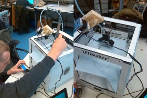
It was time for our first print! When it started printing, we saw that the printing bed wouldn’t go to the desired  height. Due to the fact an Ultimaker Original is smaller than an Ultimaker 2, the end-stops prevent the bed going higher. We managed to cheat the system a little by moving the printing bed further up while printing. This hack had to be done every time a new print starts because of the offset we applied was removed after finishing a print. Using the technique of moving the bed while printing we could print some small shapes, but the start of the print always looked bad.

first print

The distance between the nozzle and the printing bed is much to large, resulting in inaccuracy.

Calibrating and moving forward

To solve the problem permanently, the end-stops had to be disabled in the configuration.h file. By doing that the bed could go unlimited high and we could calibrate the printer. The calibrating part was done by the half of the group. The other two members worked on a way to cut the fiber each time the printer moves without extruding plastic (travel move).

victor fixt

Calibration of the Ultimaker.

We  managed to print a little cube on the right distance of nozzle and bed. We began to master the different settings of printing. The cube had some little deformation.  This is because our object cools down to quick. We are  using ABS-filament, which is very temperature sensitive. But despite that, it was a nice achievement.

99723cb8-c092-4a0b-90bb-0c90fd9ed5d3

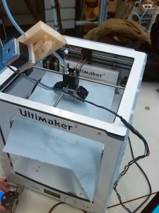
The Ultimaker, ready for print (except for the piece of paper that was used for the calibration).

The cutting device that was being designed should be placed on the printer head. This device contains a stepper motor and a spring that will move down a little, rotate a razor blade connected to the stepper motor and cut of the Kevlar fiber at the nozzle so the printer head can move freely.

5172a11c-258d-4c74-ae00-c0e796162504

Design process of the cutting mechanism.


Week 1: Get acquainted with the Ultimaker

When we first got the printer from Joris, we had to make “our” combined Ultimaker 2 work with the PCB of the Ultimaker Original. There was also a fan which had to be replaced. This fan is needed so that the filament does not solidify within the Ultimaker. Due to closure of the PMB at the IO faculty we could not ask them for a replacement, therefor we ordered one which should arrive on monday.

IMG_1213

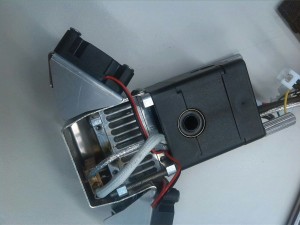
The detached nozzle head, with the missing fan.

In the meantime, we brainstormed about different solutions to the various problems that printing with fibers gives. The main challenges were the printing path, adhesion of the fibers to the filament and cutting the fiber whenever the printer has to make a move.

IMG_1212

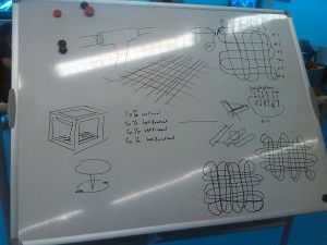
Whiteboard with our brainstorm of multiple possibilities.

We started testing some of our ideas to see which of them are achievable.

Stan tested some ways to connect the fibers to the filament, with some degree of success.